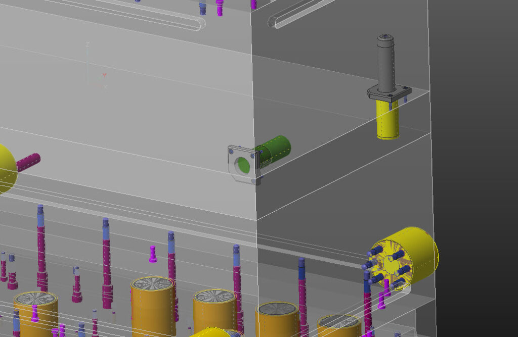

Mold Base Standard Elements
-
Overview
- These Standard Elements are all builders that reside in Mold Inset Elements. The Mold Bases allows us to incorporate these into each design without having to step into the Mold Insert Elements tool
- The standard elements will have all same options and choices that are available in the Mold Insert Elements tool
- Every Standard elements in the mold bases are editable/manipulatable. This section will go over these standard elements, how to edit them, and things to watch out for
- Every standard element shows what X & Y locations where the element will be built
- These locations are editable in the standard elements panel
- The only exception to this is FCS
- These locations are editable in the standard elements panel
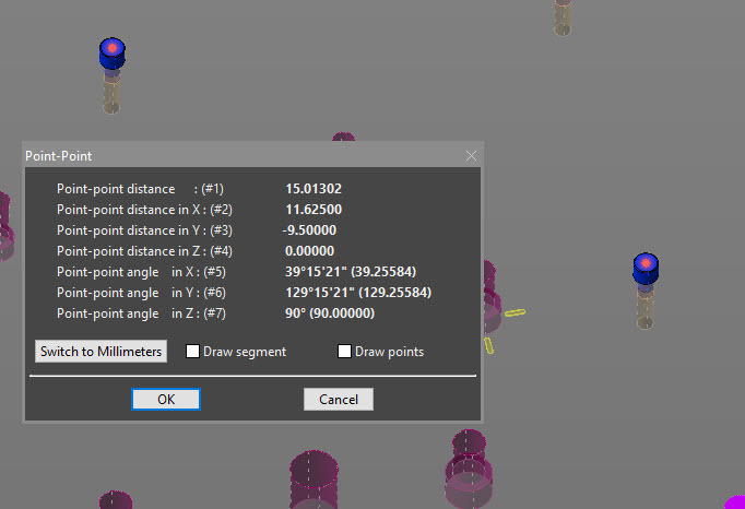
- The form also displays the distance between elements, helping the engineer verify that the spacing is up to the Engineering Standards
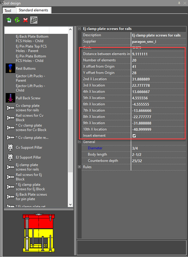
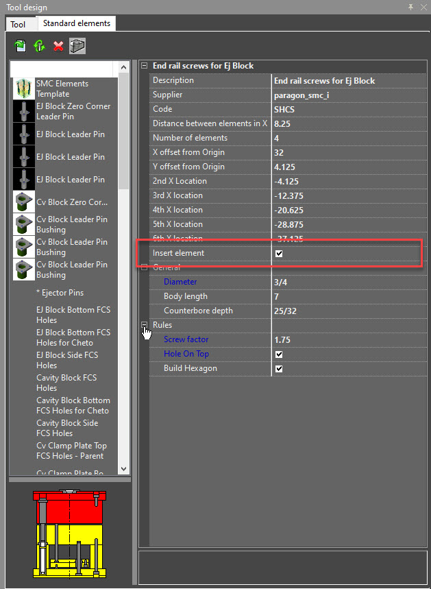
- This form also contains all the options that you would see when using the Mold Insert Elements. We can see these by expanding the “General” and “Rules” tab by clicking the box next them
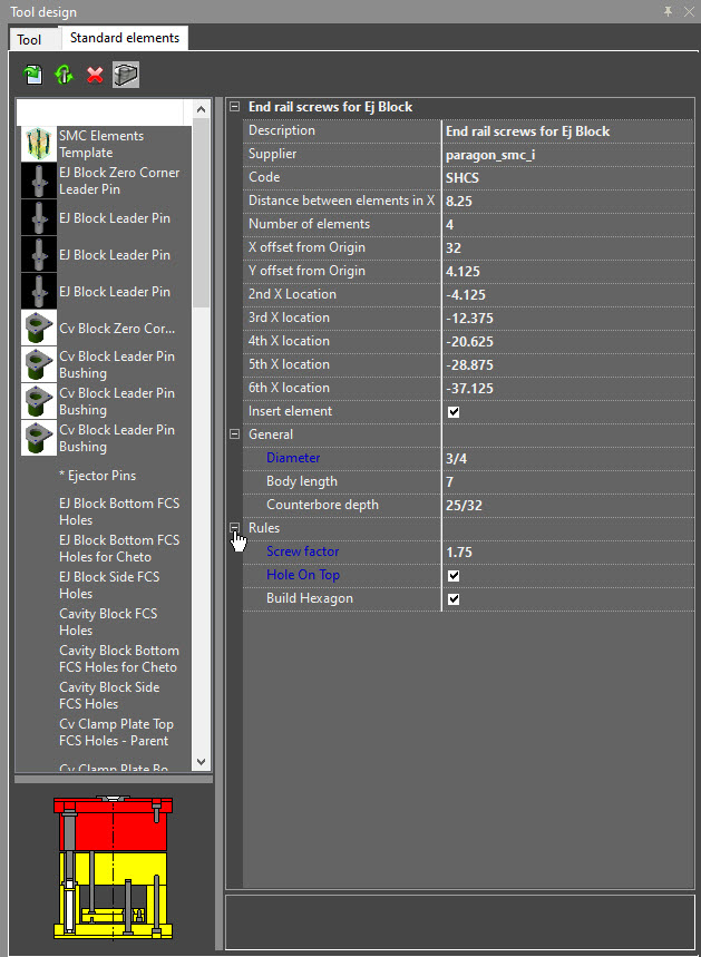
- Here we can see the other options available on the builder by expanding the rules area
- We can turn off elements in this form as well by unchecking the “Insert Element” Button
- These Standard Elements are all builders that reside in Mold Inset Elements. The Mold Bases allows us to incorporate these into each design without having to step into the Mold Insert Elements tool
-
FCS
- Every plate, cover block, and ejector block will come in with either 16mm or 24mm fcs
- Cover/Ejector Block fcs
- These blocks will come in with both 16mm and 24mm fcs
- A fcs pattern consisting of 6 16mm holes are put in the back of these blocks
- If the fcs pattern is larger than 1500mm (59.05512″), a second 4 hole 16mm fcs pattern is automatically added into the block
- This is for the Cheto gun drills, since they cannot accept an fcs pattern larger than 1500mm
- The picture below depicts the 2 different patterns, with the red squares representing the 6 hole fcs pattern that is larger than 1500mm, while the green squares represents the 4 hole fcs pattern for the Chetos
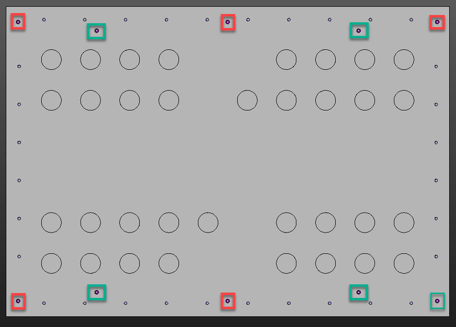
- An fcs pattern consisting of 4 24mm fcs holes are also placed into the sides of these blocks
- This pattern will never an 1500mm spacing since these are used by the Chetos for drilling on the backside of these blocks
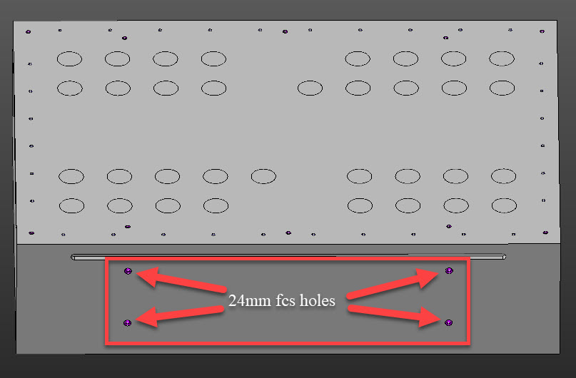
- A fcs pattern consisting of 6 16mm holes are put in the back of these blocks
- These blocks will come in with both 16mm and 24mm fcs
- Ej Back Plate, Ej Clamp Plate, and Cover Clamp Plate fcs
- These plates have a FCS pattern consisting of 6 16mm fcs holes on each side of the plate
- The fcs holes will fall onto of each other from one side to the other, meaning there will be a counterbore on both sides of the plate and a 16mm tapped hole going through the entire plate. The picture below does a better job illustrating this
- The fcs holes will fall onto of each other from one side to the other, meaning there will be a counterbore on both sides of the plate and a 16mm tapped hole going through the entire plate. The picture below does a better job illustrating this
- These plates have a FCS pattern consisting of 6 16mm fcs holes on each side of the plate
- Ej Pin Plate fcs
- The pin plate also has a fcs pattern consisting of 6 16mm fcs holes on each side of the plate
- Unlike the other plates in designs, the pin plate cannot have the fcs holes stacked on top of one another due to the thickness of this plate
- The fcs holes on one side of the plate are offset 25mm (.98425″) to one side to get around this issue, as illustrated below
- Sometimes the offset pattern causes 2 of the fcs holes to fall outside the envelope of the plate. Be sure to watch out for this situation and rectify this before subtracting
- The fcs holes on one side of the plate are offset 25mm (.98425″) to one side to get around this issue, as illustrated below
- Unlike the other plates in designs, the pin plate cannot have the fcs holes stacked on top of one another due to the thickness of this plate
- The pin plate also has a fcs pattern consisting of 6 16mm fcs holes on each side of the plate
- Cover/Ejector Block fcs
- Every plate, cover block, and ejector block will come in with either 16mm or 24mm fcs
-
Support Pillars
- Some mold bases have just Ej support pillars and some have both Cover & Ej support pillars
- Both Cover and Ej support pillars behave the same way
- The mold base does a calculation of the surface area of either the ejector or cover block between the rails and then provides builds enough support pillars to provide 10% surface area coverage
- The 10% coverage depends on the diameter of the support pillar selected. The mold bases currently default to a 4.5″ diameter support pillar. If you choose a smaller support pillar, the builder will recalculate how many support pillars will be needed for the 10% coverage
- You can add in more pillars by adjusting the number of elements. It defaults to the number needed to provide a 10% coverage area, but this can be changed.
- There is also an option for imprinting a circle for engraving that defaults to “ON”
- This provides a circle on either the cover or ejector that the machines will engrave into the back of the block
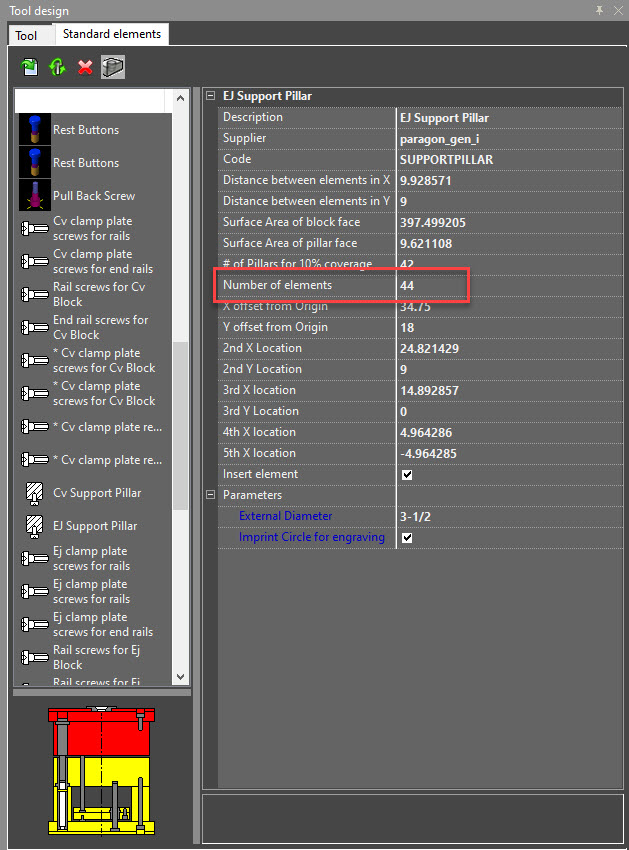
- Be diligent with the support pillars. Depending on the size of the blocks, pillars may be double placed. This would cause more pillars to be order than what is necessary.
- Also, watch out for other standard elements such as rest buttons and screws. These standard elements may fall into the support pillars, causing issues
- Some mold bases have just Ej support pillars and some have both Cover & Ej support pillars
-
Rest Buttons
- All SMC mold bases have the Rest Buttons included. They default to the 1/2″ thick Rest Buttons
- They are setup to be offset 2″ in from each end of the back plate
- Maximum spacing of 12″ between Rest Buttons along the length direction
- Maximum spacing of 10″ between Rest Buttons along the width direction
- H-Plate Templates:
- With these templates, there will be 2 Rest Button Standard Elements to select from
- One is for covering the main area underneath the Ej Back plate
- The other is for covering the area underneath the H-plate ears, as shown below
- With these templates, there will be 2 Rest Button Standard Elements to select from
- Things to be aware of:
- Depending on the job size, you may have to copy and transform a row or 2 of Rest Buttons to fill the center of the plate
- These elements may also fall into some of the Support Pillar locations
- Verify that none of the elements fall into these locations before finalizing the design
- Also verify the number of elements. Depending on the size of the job, the tool can put more than one Rest Button in a location
- All SMC mold bases have the Rest Buttons included. They default to the 1/2″ thick Rest Buttons
-
Rail Screws
- Each Mold Base is setup with rails screws. The rails screws are setup so the screws will never be longer than 8″
- If the Rail height makes it so the design needs screws longer than 8″, it switches to a double screw system
- The spacing of the screws, either the single pattern or double pattern, will follow the Engineering Standards
- All the rails in every Mold Base operate this way
- One set of screws will hold the clamp plate to the rails
- The other set will hold the rails to Cover/Ejector block
- These will be counterbored deeper in the rails to allow for an 8″ long screw to be used
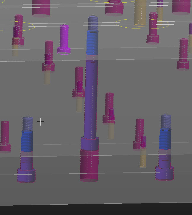
- If the design doesn’t require screws longer than 8″, the Mold Base will automatically update
- It will switch from a double screw system to a single screw system as shown below
- It will switch from a double screw system to a single screw system as shown below
- If the Rail height makes it so the design needs screws longer than 8″, it switches to a double screw system
- Things to be aware of:
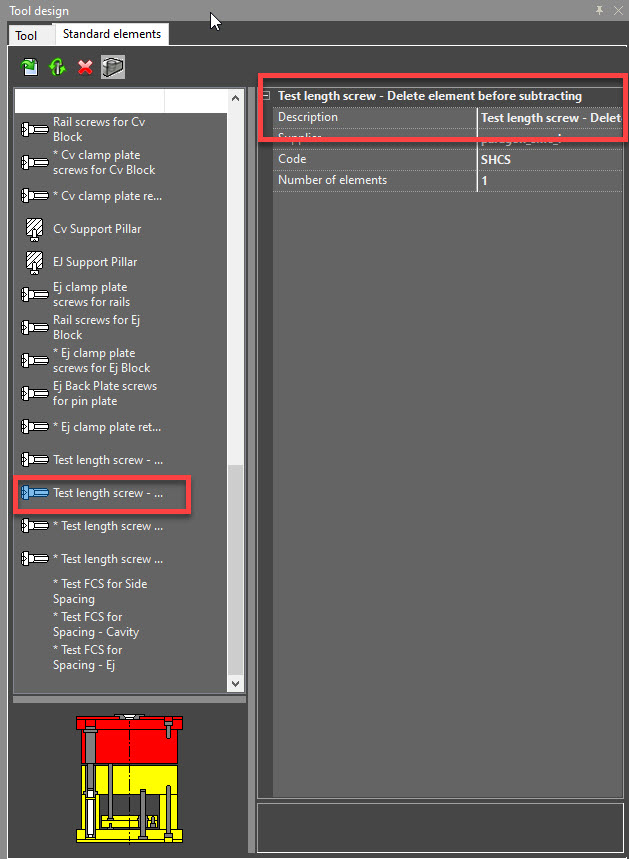
- Each mold base has at least 1 screw (some have 2) that are used to determine the body length of the rails screws. These tell the mold base to switch between a single screw pattern or a double screw pattern.
- These screws need to be deleted before subtracting the screw cavities
- They are called out by “Test length screw – Delete element before subtracting“
- H-Plate Rail Screws:
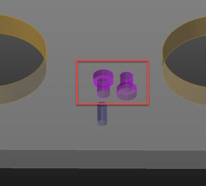
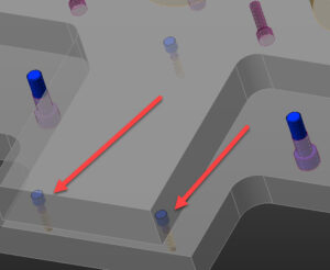
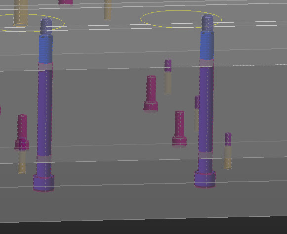
- When using the 2 screw pattern on Mold Bases that use H-Plates for both the Ej Clamp Plate and Back Plate, the clearance hole for the counterbore on the longer holes does not extend past the Ej Clamp plate as shown below:
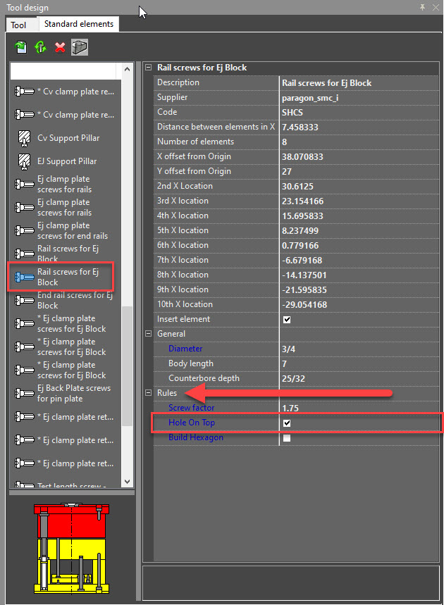
- To fix this, navigate to the screws called “Rail screws for Ej Block” and expand the rules field in the standard elements window
- The field “Hole On Top” currently checked, meaning it should be building that clearance hole above the counterbore, but this isn’t the case
- To get the hole to build properly, uncheck the box and then re-check the box
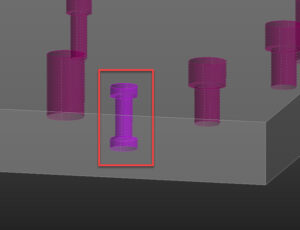
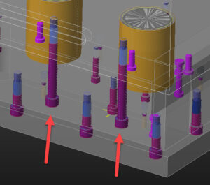
- This causes the hole to properly build as seen below:
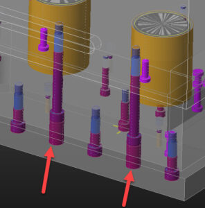
- To get the hole to build properly, uncheck the box and then re-check the box
- When using the 2 screw pattern on Mold Bases that use H-Plates for both the Ej Clamp Plate and Back Plate, the clearance hole for the counterbore on the longer holes does not extend past the Ej Clamp plate as shown below:
- Each mold base has at least 1 screw (some have 2) that are used to determine the body length of the rails screws. These tell the mold base to switch between a single screw pattern or a double screw pattern.
- Each Mold Base is setup with rails screws. The rails screws are setup so the screws will never be longer than 8″
-
Ej Back Plates Screws
- Screws for attaching the pin plate to the back plate
- These default to a 1/2″ screw
- Setup with an 8″ offset from the edge of the back plate
- 2″ offset from the side of the back plate
- Maximum spacing of 12″ between screws
- Things to be aware of:
- Depending on the job size, you may have to copy and transform a row or 2 of these screws to fill the center of the plate, which is illustrated below:
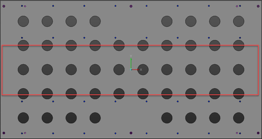
- We can see that there is 2 rows of screw missing in the area outlined by the red square. Transforming over a row of screws and making multiple copies will take care of this issue
- These elements may also fall into some of the Support Pillar locations
- Verify that none of the elements fall into these locations before finalizing the design
- Depending on the job size, you may have to copy and transform a row or 2 of these screws to fill the center of the plate, which is illustrated below:
- Screws for attaching the pin plate to the back plate
-
Pull Back Screws
- Every Mold Base also includes 6 pull back screws
- This builder only builds the cavity of the screw and the identification markings around the counterbore for the screw head
- It does not build or place a screw into the assembly
- The X & Y locations are editable, allowing you to move them around in order to miss other standard components such as support pillars, FCS holes, pins, or other screws
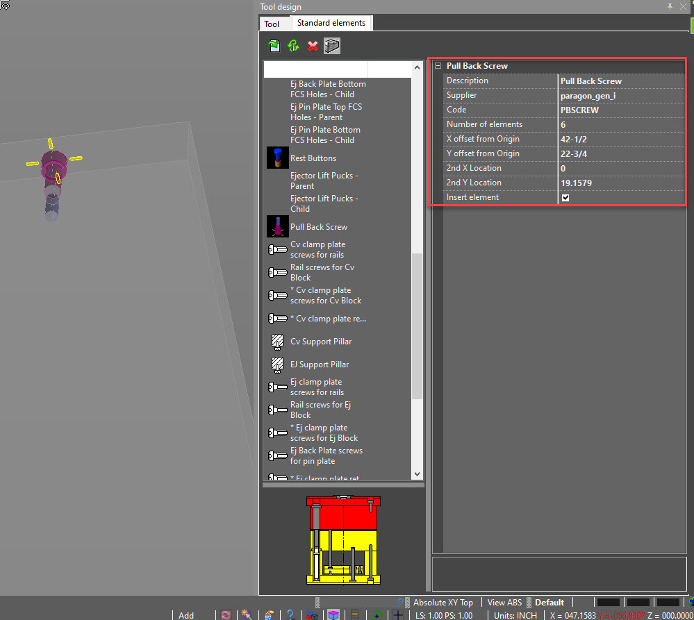
- This builder only builds the cavity of the screw and the identification markings around the counterbore for the screw head
- Every Mold Base also includes 6 pull back screws
-
Lift Pucks
- Some Mold Bases will have lift pucks on the Ejector. There are 2 sets of lift pucks, one for each side of the tool. One is labelled parent and the other is labelled child
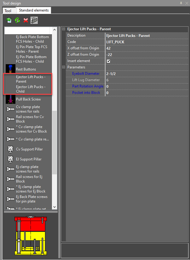
- The child Lift Lug references the parent Lift Lug for X & Z locations, Eyebolt Diameter, and inserting the element
- If the X & Z location for the parent Lift Lug are modified, the child Lift Lug will be updated to those X & Z Locations
- Updating the Diameter of the parent will also update the child
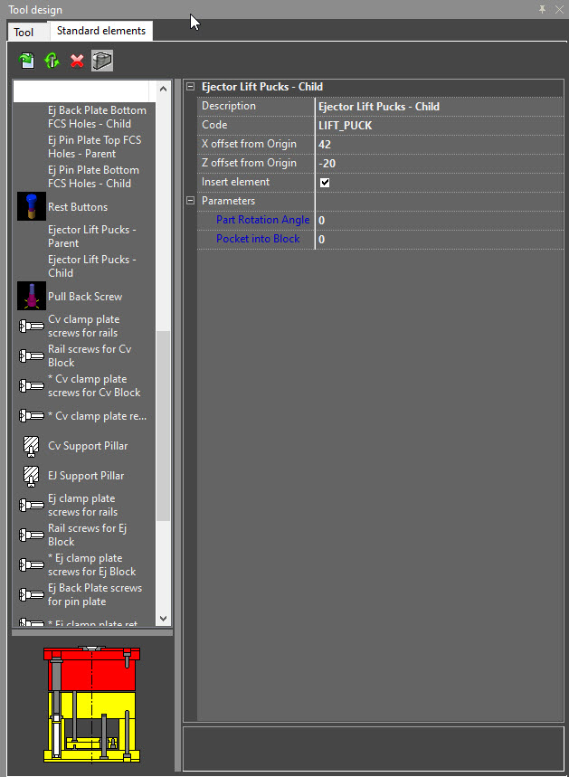
- We can see on the child Lift Lug that there is no option for eyebolt diameter, since this is controlled by the parent Lift Lug
- You can change the X & Z location, but if you update the parent, the child will update as well
- Some Mold Bases will have lift pucks on the Ejector. There are 2 sets of lift pucks, one for each side of the tool. One is labelled parent and the other is labelled child
-
Leader Pins
- Each Mold Base contains 4 leader pins
- One is labelled Zero Corner Leader Pin that is offset a 1/4″ compared to the other 3 leader pins
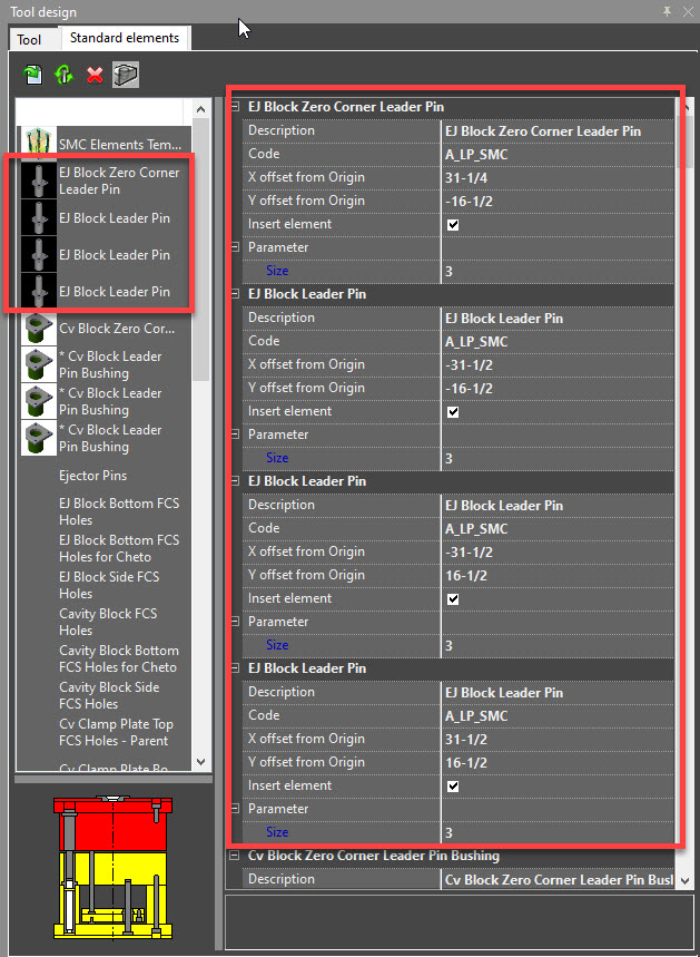
- The leader pins are setup similarly to the lift lugs, with the zero corner leader pin being the parent and the other 3 being the child
- If you change the size on the zero corner leader pin, it will cause the other 3 leader pins to update to that same size
- When you update the size of the leader pin, it also updates the leader pin bushing size to match
- Each Mold Base contains 4 leader pins
-
Leader Pin Bushings
- Each Mold Base contains 4 leader pin bushings
- One is labelled Zero Corner Leader Pin Bushing that is offset a 1/4″ compared to the other 3 leader pin bushings
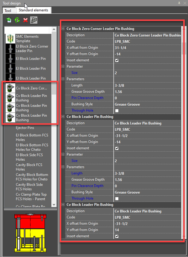
- The leader pin bushings are setup similarly to the lift lugs, with the zero corner leader pin bushings being the parent and the other 3 being the child
- If you change the size on the zero corner leader pin, it will adjust the size of the 4 leader pin bushings to match
- Things to be aware of:
- If the mold base has a negative injection opening, it will cause the leader pin bushings to not build
- This is due to the leader pin bushings wanting to build sideways
- This is due to the leader pin bushings wanting to build sideways
- If the mold base has a negative injection opening, it will cause the leader pin bushings to not build
- Each Mold Base contains 4 leader pin bushings